APPENDIX C: QUANTITATIVE ANALYSIS
The objective of this quantitative analysis is to determine the amount of torque lost in using the altered crank arm versus the original unaltered crank arm. We also investigated the potential benefits of installing an eccentric chain ring [1]. We calculated and compared the torque for multiple crank arm lengths and used the peak torque for each length to calculate the percent of the maximum possible torque each length obtains. To investigate the improvements an eccentric chain ring might offer, we calculated the gain ratio as a function of the crank arm length and the radius ratio [2]. A second component of the quantitative analysis involved determining the minimum diameter of the shoulder screw necessary to withstand the shear force applied by the user.
Torque Analysis:
Torque (τ![]() ) is a vector measurement of an object’s tendency to rotate around some axis and is calculated as a cross product of the length of the lever arm (l) and the force being applied (F):τ
) is a vector measurement of an object’s tendency to rotate around some axis and is calculated as a cross product of the length of the lever arm (l) and the force being applied (F):τ![]() = l x Fwhich further simplifies to a function of the angle of rotation: τ
= l x Fwhich further simplifies to a function of the angle of rotation: τ![]() = l F sin(Θ
= l F sin(Θ![]() ) where Θ
) where Θ![]() is the angle between F and l.
is the angle between F and l.
In our design, the crank arm plays the part of the lever arm (l) to which a constant force (F) is applied as the rider pedals. We assume that this force is applied in the downward direction during the downstroke on both the left and the right side. Because the pedaling motions on either side of the bicycle directly oppose one another, when the left foot is not applying any downward force during the upstroke the right foot is able to apply the necessary force because it is in the downstroke. The rider is always exerting some downward force due to the fact that the two sides are exactly 180° out of phase with one another.
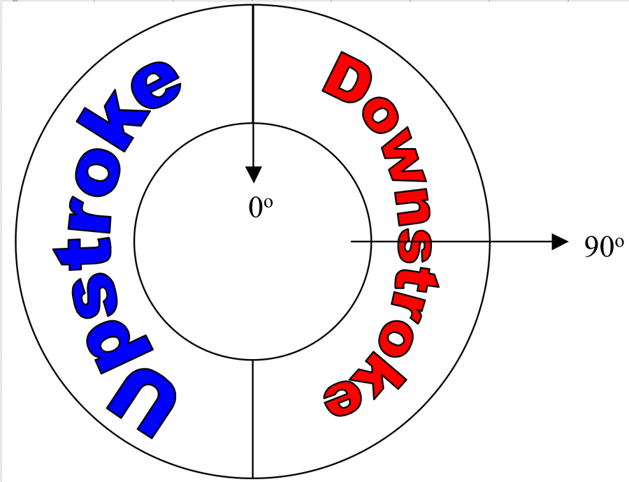
Figure C-1: parts of a full pedal cycle
Using Matlab, we calculated the torque for three different crank arm lengths through two complete pedal cycles of 360°. The crank arm lengths used represent the length of the shortest possible setting on the adjustable prototype, the length of the final assembly, and the length of an unaltered crank arm.
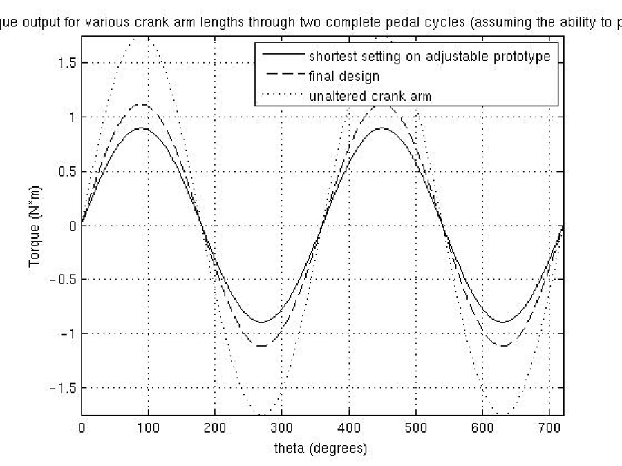
Figure C-2: Torque output for various crank arm lengths through two complete pedal cycles (assuming the ability to pull up)
Figure C-2 shows that the altered crank arms result in significantly less torque than the unaltered crank arm length. The positive portions of the sine wave represent the times when force is being applied to the left pedal while the negative portions correspond to when force is being applied to the right pedal. The peak of each sine wave occurs at 90° meaning that maximum torque is achieved when the force is applied at a right angle to the lever arm. When this maximum output is plotted against crank arm length, a clear trend emerges (Figure C-3).
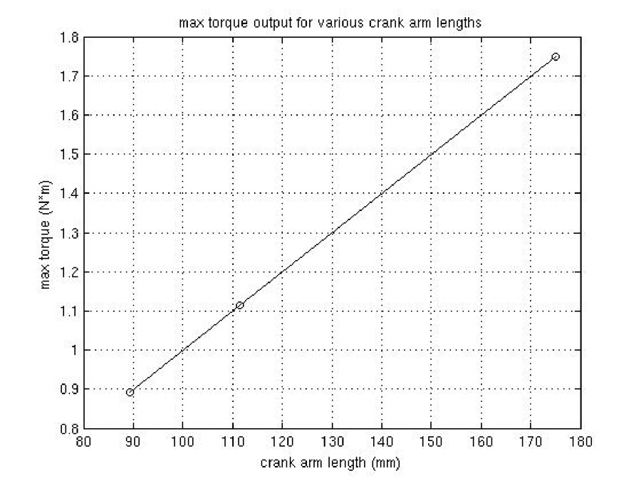
Figure C-3: maximum torque output for various crank arm lengths
Figure C-3 reveals that the maximum torque is a linear function of crank arm length. This result is expected from the underlying mathematics. The function of torque as stated previously is τ![]() = l F sin(Θ
= l F sin(Θ![]() ), and because the applied force and the value for theta are constant for all maximum (and minimum) torque values, τ
), and because the applied force and the value for theta are constant for all maximum (and minimum) torque values, τ![]() max = l F sin(90°)
max = l F sin(90°)![]() = l F. Therefore, as the crank arm length varies the maximum torque value changes proportionally. When normalized, one can clearly see that the maximum torque achieved with the final design is only 63.7% of the torque achieved when using an unaltered crank arm (Figure C-4).
= l F. Therefore, as the crank arm length varies the maximum torque value changes proportionally. When normalized, one can clearly see that the maximum torque achieved with the final design is only 63.7% of the torque achieved when using an unaltered crank arm (Figure C-4).
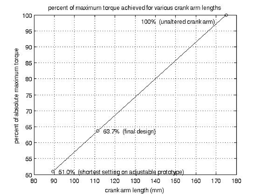
Figure C-4: Percent of the maximum possible torque achieved by crank arms of various lengths
The above analysis reveals that altering the crank arm length increases the amount of force that the user must apply in order to see the same results expected from an unaltered arm. One solution that has been investigated to offset this power loss is the installation of an eccentric chain ring [1]. The eccentric chain ring alters both the crank arm length and the radius ratio (number of teeth in the front chain ring to the number of teeth in the back chain ring) as the user pedals by utilizing a complex sliding mechanism.
In order to model the effects an eccentric chain ring would have on the performance of the pivoting crank arm, we employed the measurement of a gain ratio: GR = (WR/l) × (T![]() F /T
F /T![]() R ), where GR is gain ratio, WR is wheel radius, lis the length of the crank arm, T
R ), where GR is gain ratio, WR is wheel radius, lis the length of the crank arm, T![]() F is the number of teeth in the front chain ring, and T
F is the number of teeth in the front chain ring, and T![]() R is the number of teeth in the rear chain ring [2]. The gain ratio essentially quantifies gear changes as the user cycles. Larger values for the gain ratio mean that the user must work harder but “gets more out of it,” essentially corresponding to a higher gear level. A smaller value for the gain ratio indicates easier effort but less ground covered, equivalent to a lower gear level. Using this measurement, we were able to evaluate the effect an eccentric chain ring would have on the pedaling action.
R is the number of teeth in the rear chain ring [2]. The gain ratio essentially quantifies gear changes as the user cycles. Larger values for the gain ratio mean that the user must work harder but “gets more out of it,” essentially corresponding to a higher gear level. A smaller value for the gain ratio indicates easier effort but less ground covered, equivalent to a lower gear level. Using this measurement, we were able to evaluate the effect an eccentric chain ring would have on the pedaling action.
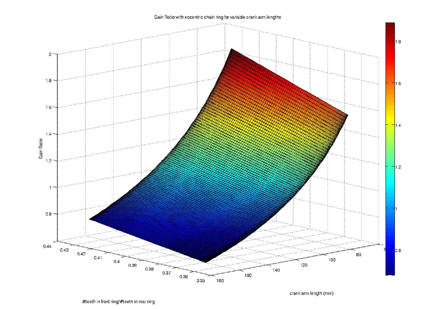
Figure C-5: gain ratio with eccentric chain ring for variable crank arm lengths
Figure C-5 shows that as the crank arm length increases and the radius ratio decreases, the gain ratio also decreases, indicating that the bicycle becomes easier to pedal. The minimum radius ratio and maximum crank arm length are achieved at 90° during the pedal rotation, making the bicycle easier to pedal at the moment when the most force is being applied. This trend suggests that the eccentric chain ring could be an excellent addition to our pivoting crank arm design because it would allow the rider to apply more force at the most opportune location in the pedal cycle. We believe that such a modification could be beneficial and should be investigated for future improvement.
Shoulder Screw Analysis:
A concern arose during construction that the diameter of the shoulder screw was a vital dimension in the stability of the pivoting crank arm. In order to determine the minimum diameter necessary to avoid shear failure, we conducted the following analysis.
The definition of the factor of safety for tensile strength is Factor of Safety = (Sy)/(σ![]() 2
2 x + 3τ
![]() 2 xy)1/2 , [3] where σ
2 xy)1/2 , [3] where σ![]() x is the tensile stress and τ
x is the tensile stress and τ![]() xy is the shear stress. The definition for single shear stress is &tau = (4F)/(πd2), where F is the maximum force applied and d is the diameter of the shoulder screw. By assuming no tensile stress and safety factor of one, combining the two equations shows the diameter to be d = ((4F(3)1/2)/(πSy))
xy is the shear stress. The definition for single shear stress is &tau = (4F)/(πd2), where F is the maximum force applied and d is the diameter of the shoulder screw. By assuming no tensile stress and safety factor of one, combining the two equations shows the diameter to be d = ((4F(3)1/2)/(πSy))![]() 1/2 . Using a downward force of 300 lbs and the tensile strength of 18-8 stainless steel (74,700 psi), the minimum diameter to avoid failure from shearing is 0.0595”. This is well below the 5/16” used on the shoulder bolt, and thus makes shearing failure an insignificant issue.
1/2 . Using a downward force of 300 lbs and the tensile strength of 18-8 stainless steel (74,700 psi), the minimum diameter to avoid failure from shearing is 0.0595”. This is well below the 5/16” used on the shoulder bolt, and thus makes shearing failure an insignificant issue.
We learned that the screw was bending due to forces being applied non-perpendicularly to the shoulder screw, rather than due to shear, perpendicular forces. This occurred due to a gap between the sections of the crank arm. This problem was resolved by ordering another thrust bearing and filling in this space completely.
REFERENCES
- Hue, Olivier et al. “Enhancing cycling performance using an eccentric chainring.”
Official Journal of the American College of Sports Medicine. 2001.
- Brown, Sheldon. “Gain Ratios—A New Way to Design Bicycle Gears.”
SheldonBrown.com. 1995. http://www.SheldonBrown.com/gain.html.
- Beardmore, Roy. “Bolted Joint.” RoyMech. 2008.
http://www.RoyMech.co.uk/Useful_Tables/Screws/Bolted_Joint.html.